

Requirements For Flex PCBs
The bending endurance of a flexible circuit is the ability to withstand repeated bending without degradation in performance. This is a crucial design specification for many dynamic applications such as motors, sensors and controls. To achieve this, the board must be optimized for flexing by implementing air gaps, copper grain direction optimization and other factors such as the thickness of the copper-clad laminate (CCL), etching techniques and adhesive system selection.
In addition, the material used in the stiffener is critical to achieving a high bending endurance. Aluminum or polyimide are popular choices. These materials are strong and durable, have excellent electrical conductivity and low coefficient of thermal expansion (CTE) to handle temperature fluctuations. They also provide excellent insulation properties. However, they are not suitable for direct contact with moisture and must be treated to avoid corrosion. A good solution is to use an aluminum-based flex PCB with an anodized layer that provides the needed resistance to corrosion and handling damage, and provides a high level of insulation.
A key difference between a printed circuit board and a flexible circuit is the fact that a flex can bend, twist and fold while a rigid board cannot. This creates a new set of design rules and requirements for the construction of a flex circuit and requires the use of different materials. These differences also introduce additional complexities in the manufacturing process such as registration tolerances, chemical and physical properties of the materials and assembly methods.
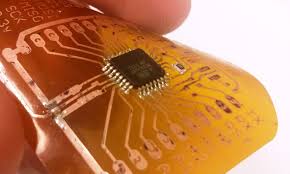
Bending Endurance Requirements For Flex PCBs
To increase the bending endurance of a flex circuits, it is important to minimize the number of layers in the CCL as well as the copper thickness. These two factors directly affect the bend radius. It is also important to route traces away from the bend area. It is also a good idea to stagger traces rather than stacking them one on top of another. This will prevent the i-beam effect that can occur when traces are stacked one on top of each other.
Flex PCBs are widely used in many different types of devices including calculators, mobile phones, printers and LCD televisions. They are also used in medical equipment such as pacemakers and hearing aids. Other applications include data communication, optical networking and industrial control.
A flex circuit must meet IPC 2223 standards for the minimum allowable copper elongation and bend radius. This is an estimation formula that helps engineers design a flex circuit with the correct elongation capability to avoid tearing or damage to the copper traces during bending. The flex circuit should be free from features like mounting holes, slots and cutouts to reduce stress on the elongated portions of the flex.
It should be connected to the rigid portion of the board using an insulating adhesive system that can withstand high temperatures and mechanical forces. It is also a good idea to use an aluminum or FR4 stiffener in the rigid section of the circuit to ensure the highest bending capability. These stiffeners can be bonded using an epoxy, acrylic or pressure-sensitive adhesive to provide the desired flexability.


